信号源
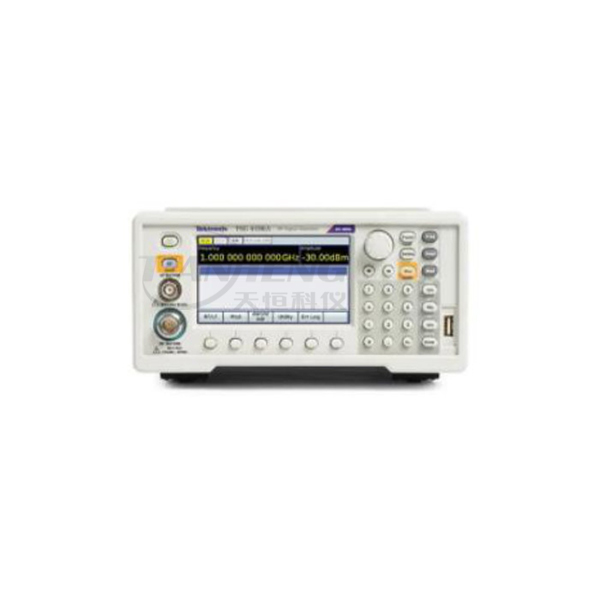
TSG4100A 系列 RF 信号发生器以入门级射频信号发生器的价格提供中等射频性能和高达 200MHz 的超宽调制带宽。 方便的现场升级软件允许工程师轻松将设备的模拟调制功能升级为矢量调制和数字调制功能,从而提供灵活的配置和的 CAPEX 保护。
用于模拟和数字应用的 RF 信号发生器
TSG4100A 系列 RF 信号发生器同时具有模拟和更的矢量和数字调制功能,成本非常低。工程师可以简便地从模拟信号转向矢量信号,从而提供灵活的配置和的 CAPEX 保护。这些低成本 RF 信号发生器内置支持常见的矢量调制方案,包括 ASK、QPSK、DQPSK、π/4 DQPSK、8PSK、FSK、CPM、QAM(4 至 256)、8VSB 和 16VSB。


内部带宽高达 6MHz 的射频信号发生器
凭借创新的 I/Q 调制架构,用户友好的 TSG4100A 系列提供快速波形生成并支持纯数字数据的播放。仪器以高达 6 MHz 的符号速率把数字符号映射到选定的 I/Q 星座中,把结果传送到选定的脉冲整形滤波器中,生成以 125 MHz 实时更新的终波形。然后这个基带信号使用标准 IQ 调制技术调制到 RF 载波上。
使用 RF 信号发生器的 OCXO 时基
TSG4100A 系列仪器使用恒温箱控制的 SC 切割晶振时基,稳定性提高了 100 倍 (<±0.002ppm),与使用 TCXO 时基的仪器相比,近距离相位噪声降低了 100 倍。还可以为研发应用提供的时效 (<±0.05ppm)。


TSG4100A 射频信号发生器上的 RF 信号播放
TSG4100A RF 信号发生器具有使用外部 IQ 信号的选项,该选项可为高载波频率(如 400MHz 以上的载波频率)提供 200MHz 以上的射频调制带宽。了解如何使用通过 RSA 捕获的 RF 信号以及 SourceXpress 应用程序格式化基带 IQ 信号,然后了解如何设置 AFG31000 任意函数发生器以驱动 TSG 上的 IQ 输入。
使用AFG3100再TSG4100A上播放捕捉的RF信号
RF 信号发生器常见问题
RF 信号发生器的用途是什么?

射频 (RF) 信号发生器用于创建具有已知特性的连续射频信号,以测试电路设计,主要是通信设备中的电路设计。RF 信号发生器本身不进行任何测量,它只是为其他仪器设置正确的条件来测量被测设备。
RF 发生器如何工作?
RF 信号发生器通常是一种信号源,用于测试开发用于 RF 通信(例如无线和蜂窝通信、雷达、电子战等)的电路。工程师可以使用系统控制设置幅度、频率并对信号应用调制。
如何生成 RF 频率?
生成 RF 频率的简单方法是使用 TSG4100A RF 信号发生器的前面板。在将 RF 信号发生器连接至被测设备 (DUT) 前,您可以轻松设置频率、幅度、调制和许多其他信号特性。
信号发生器和函数发生器有何区别?
信号发生器是任何产生电子信号的设备。矢量信号发生器专门使用模拟和数字调制方案以 QAM、QPSK、FSK、BPSK 和 OFDM 等格式创建射频信号。矢量信号发生器通常用于接收机灵敏度测试。
函数发生器具有其可播放的预设波形或模式列表。操作员可以更改波形参数,例如播放速度、幅度和偏置,或添加基本失真或调制。
信号发生器的类型有哪些?
信号发生器的类型有很多,包括函数发生器、任意波形发生器和矢量信号发生器。
查看下表了解每种类型之间的差异。
| 信号发生器 | 模拟和数字电子信号源的通用类别名称。 |
| 函数发生器 | 如需正弦波、三角波等常见波形,则通常使用信号发生器。 |
| 任意函数发生器 | 函数发生器能够产生任意编译波形。 |
| 任意波形发生器 | 如需自定义编译波形(而不是预设常用波形),则主要使用任意波形发生器。 |
| RF 信号发生器 | RF 信号发生器用于无线应用,通常提供正常的模拟调制,例如 AM、FM 和 PM。 |
| (RF) 矢量信号发生器 | 对于数字通信应用,RF 矢量信号发生器支持对 RF 载波进行模拟和矢量调制。 |
Specifications
All specifications are guaranteed unless noted otherwise. All specifications apply to all models unless noted otherwise.Frequency
BNC output, all models
DC to 62.5 MHz
N-type outputs
TSG4102A
950 kHz to 2.0 GHz
TSG4104A
950 kHz to 4.0 GHz
TSG4106A
950 kHz to 6.0 GHz
Frequency resolution
1 μHz at any frequency
Switching speed
<8 ms (to within 1 ppm)
Frequency error
<(10–18 + time-base error) × fc
Frequency stability
1 × 10–11 (1 s Allan variance)
Front panel BNC output
Frequency range
DC to 62.5 MHz
Amplitude
1.00 VRMS to 0.001 VRMS (-47 dBm to +14.96 dBm)
Offset
±1.5 VDC
Offset resolution
5 mV
Maximum excursion
1.817 V (amplitude + offset)
Amplitude resolution
<1 %
Amplitude accuracy
±0.7 dB
Harmonics, typical
<–40 dBc
Spurious, typical
<–65 dBc
Output coupling
DC, 50 Ω ±2%
Impedance
50 Ω
Reverse protection
±5 VDC
VSWR, typical
< 1.6 :1
Front panel N-type output
Power output
TSG4102A
+16.5 dBm to –110 dBm
TSG4104A
+16.5 dBm to –110 dBm (<3 GHz)
TSG4106A
+16.5 dBm to –110 dBm (<4 GHz) +10 dBm to –110 dBm (4-6 GHz)
Voltage output
TSG4102A
1.5 VRMS to 0.7VRMS
TSG4104A
1.5 VRMS to 0.7 μVRMS (<3 GHz)
TSG4106A
1.5 VRMS to 0.7 μVRMS (<4 GHz)
Amplitude resolution
0.01 dBm
Amplitude accuracy
CW, 50 Ω load (dB, typical)
CW, 18 °C to 28 °C >10 dBm 10 to -30 dBm -30 to -60 dBm -60 to -100 dBm <-100 dBm 10 MHz to 0.1 GHz ±0.2 ±0.25 ±0.35 ±0.45 ±0.6 0.1 GHz to 2 GHz ±0.15 ±0.15 ±0.25 ±0.35 ±0.6 2 GHz to 4 GHz ±0.3 ±0.2 ±0.35 ±0.6 ±0.8 4 GHz to 6 GHz NA ±0.3 ±0.4 ±0.75 ±1.25 CW, 50 Ω load (dB, max)
Level range: +5 to -30 dBm (max) +5 to -30 dBm (typical) Temperature: 18 °C to 28 °C 5 °C to 40 °C 5 °C to 40 °C 10 MHz to 0.1 GHz ±0.6 ±1.0 ±0.7 0.1 GHz to 2 GHz ±0.6 ±1.0 ±0.6 2 GHz to 4 GHz ±0.6 ±1.0 ±0.7 4 GHz to 6 GHz ±1 ±1.5 ±0.9
Impedance
50 Ω
Output coupling
AC, 50 Ω
VSWR, typical
<1.5 (2 MHz to 2 GHz) <1.8 (2 GHz to 6 GHz)
Reverse protection
30 VDC, +25 dBm
IQ modulation output level accuracy
Output amplitude is -5 dBm.
Temperature: 18 °C to 28 °C 5 °C to 40 °C Fc: Typical (dB) Max (dB) Typical (dB) <2 GHz ±0.1 ±0.4 ±0.4 2 GHz to 4 GHz ±0.2 ±0.6 ±0.4 4 GHz to 6 GHz ±0.4 ±0.8 ±0.7
Spectral purity of the RF output
Subharmonics
None
Harmonics, maximum
Output level<0 dBm, 1 GHz CW signal
TSG4102A and TSG4104A
< -38 dBc
TSG4106A
< -30 dBc
Harmonics, typical (output level < 0 dBm)
< -35 dBc, CW , Fc < 2 GHz
Spurious (typical)
Output level -10 dBm, CW
< -68 dBc
>10 kHz from carrier in 950 kHz to 1 GHz
< -60 dBc
>10 kHz from carrier in 1 GHz to 2 GHz
< -55 dBc
>10 kHz from carrier in 2 GHz to 4 GHz
< -55 dBc
>10 kHz from carrier in 4 GHz to 6 GHz
Residual FM, typical
1 Hz rms (300 Hz to 3 kHz bandwidth)
Residual AM, typical
0.006 % rms (300 Hz to 3 kHz bandwidth)
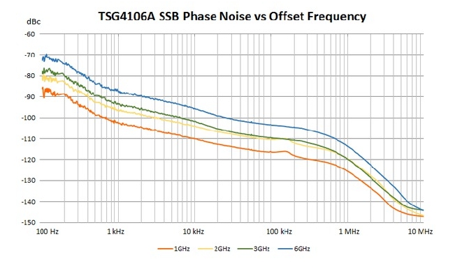
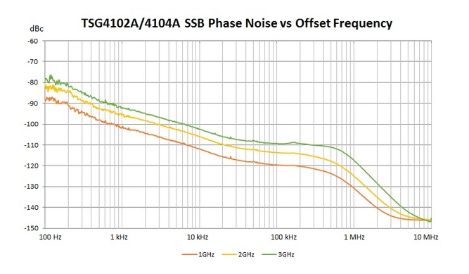
SSB phase noise
Output level is +5 dBm at 18 °C to 28 °C.
Carrier Offset from carrier, typical (dBc/Hz) 1 kHz 10 kHz 20 kHz 1 MHz 1 GHz -102 -110 -113 -124 2 GHz -96 -104 -107 -118 3 GHz -93 -102 -105 -120 6 GHz -87 -96 -99 -114
SSB phase noise at 1 GHz carrier, maximum (output level +5 dBm, 5 ℃ to 40 ℃)
1 kHz offset
–95 dBc/Hz
10 kHz offset
–106 dBc/Hz
20 kHz offset
–107 dBc/Hz
1 MHz offset
–120 dBc/Hz
2 GHz offset
–118 dBc/Hz
>3 GHz offset
–120 dBc/Hz


Phase setting (front panel outputs)
Maximum phase step
±360º
Phase resolution
0.01º (DC to 100 MHz) 0.1º (100 MHz to 1 GHz) 1.0º (1 GHz to 6 GHz)
OCXO time-base (Option M00 or Option E1)
Oscillator type
Oven-controlled, 3rd OT, SC-cut crystal
Initial accuracy at calibration (20 minute warm-up, at 18 ºC to 28 ºC)
<±0.02 ppm
Temperature drift (0 ºC to 40 ºC)
<±0.003 ppm
Aging
<±0.05 ppm/year
VCXO time base (Option M01)
Initial accuracy at calibration (20 minute warm-up, at 18 ºC to 28 ºC)
<±0.5 ppm
Temperature drift (0 ºC to 40 ºC)
<±5.0 ppm
Aging
<±3.0 ppm/year
Time-base input
Frequency
10 MHz, ±2 ppm
Amplitude
0.5 VP-P to 4 VP-P (–2 dBm to +16 dBm)
Input impedance
50 Ω, AC coupled
Time-base output
Frequency
10 MHz, sine
Source
50 Ω, DC transformer coupled
Amplitude
>7.5 dBm
Internal modulation source
Waveforms
Sine, ramp, saw, square, pulse, noise
Sine THD
–74 dBc (typical at 20 kHz)
Ramp linearity
<0.05 % (1 kHz)
Rate
TSG4102A and TSG4104A
1 μHz to 500 kHz: < 62.5 MHz CF 1 μHz to 50 kHz: ≥62.5 MHz
TSG4106A
1 μHz to 500 kHz: < 93.75 MHz CF 1 μHz to 50 kHz: ≥93.75 MHz
Rate resolution
1 μHz
Rate error
1:231 + time-base error
Noise function
White Gaussian noise (rms = dev / 5)
Noise bandwidth
1 μHz < ENBW < 50 kHz
Pulse generator period
1 μs to 10 s
Pulse generator width
100 ns to 9999.9999 ms
Pulse timing resolution
5 ns
Pulse noise function
Length 2N-1 PRBS 5 ≤ N ≤ 32, bit period 100 nS to 10 S
Analog modulation output
Connector type
BNC (rear panel)
Impedance
50 Ω
Function
AM, FM, ΦM, Pulse
Scale factor
±1 V for ± full deviation
Pulse/Blank
Low = 0 V Hi = 3.3 V
External analog modulation input
Connector type
BNC (rear panel)
Impedance
100 kΩ
Function
AM, FM, ΦM, Pulse
Scale factor
±1 V for ± full deviation
Pulse/Blank
Low = 0 V Hi = 3.3 V
Input coupling
DC or 4 Hz High-pass
Pulse Threshold
+1 VDC
Input Offset
< 500 μV
Amplitude modulation
Range
0 to (decreases above +7 dBm)
Resolution
0.1%
Modulation source
Internal or external
Modulation distortion, typical
BNC output
<1 % (fc < 62.5 MHz, fm = 1 kHz)
N-type output
Modulation bandwidth (external)
>100 kHz
Frequency modulation
Minimum frequency deviation
0.01 Hz
Maximum frequency deviation
TSG4102A and TSG4104A
Smaller of fc and 64 MHz – fc. In 0 to 62.5 MHz
Frequency range Maximum deviation 62.5 MHz < fc ≤ 126.5625 MHz 1 MHz 126.5625 MHz < fc ≤253.1250 MHz 2 MHz 253.1250 MHz < fc ≤ 506.25 MHz 4 MHz 506.25 MHz < fc ≤ 1.0125 GHz 8 MHz 1.0125 GHz < fc ≤ 2.0 GHz 16 MHz 2.025 GHz < fc ≤ 4.0 GHz (TSG4104A) 32 MHz TSG4106A
Smaller of fc and 96 MHz – fc. In 0 to 93.75 MHz
Frequency range Maximum deviation 93.75 MHz < fc ≤ 189.84375 MHz 1 MHz 189.84375 MHz < fc ≤ 379.6875 MHz 2 MHz 379.6875 MHz< fc ≤ 759.375 MHz 4 MHz 759.375 MHz < fc ≤ 1.51875 GHz 8 MHz 1.51875 GHz < fc ≤ 3.0375 GHz 16 MHz 3.0375 GHz < fc ≤ 6.0 GHz 32 MHz
Deviation resolution
0.1 Hz
Deviation accuracy, typical
TSG4102A and TSG4104A
< 0.1% of selected deviation + 5 Hz (fc < 62.5 MHz) < 2% of selected deviation + 20 Hz (fc > 62.5 MHz)
TSG4106A
< 0.1% of selected deviation + 5 Hz (fc < 93.75 MHz) < 2% of selected deviation + 20 Hz (fc > 93.75 MHz)
Modulation source
Internal or external
Modulation distortion, typical
< -60 dB (fc=100 MHz, fm=1 KHz, fd= 3 KHz)
External FM carrier offset, typical
< ±0.001 X FM deviation
Modulation bandwidth, typical
TSG4102A and TSG4104A
500 kHz (fc < 62.5 MHz) 100 kHz (fc > 62.5 MHz)
TSG4106A
500 kHz (fc < 93.75 MHz) 100 kHz (fc > 93.75 MHz)
Phase modulation
Deviation
0º to 360º
Deviation resolution, typical
0.01º (DC to 100 MHz) 0.1º (100 MHz to 1 GHz) 1º (1 GHz and above)
Deviation accuracy, typical
TSG4102A and TSG4104A
2% (fc < 62.5 MHz) 3% (fc > 62.5 MHz)
TSG4106A
2% (fc < 93.75 MHz) 3% (fc > 93.75 MHz)
Modulation source
Internal or external
Modulation distortion, typical
< -60 dB (fc = 100 MHz, fm =1 kHz, ΦD = 50º)
Modulation bandwidth, typical
TSG4102A and TSG4104A
500 kHz (fc < 62.5 MHz) 100 kHz (fc > 62.5 MHz)
TSG4106A
500 kHz (fc < 93.75 MHz) 100 kHz (fc > 93.75 MHz)
Pulse modulation
Pulse mode
Logic High turns RF output ON
On-Off ratio, typical
BNC output
> 70 dB
Type-N output
> 57 dB (fc < 1.0 GHz) > 40 dB (1.0 GHz ≤ fc < 4.0 GHz) > 35 dB (4.0 GHz ≤ fc < 6.0 GHz)
Pulse feed-through, typical
10% of carrier for 20 ns at turn on
Turn On-Off delay
60 ns
RF Rise-Fall time, typical
20 ns
Modulation source
Internal or external pulse
Interface connectors
USB
USB 2.0, host
Ethernet (LAN)
10/100 Base-T.TCP/IP and DHCP default
GPIB
IEEE488.2
RS-232
4800 to 115,200 baud, RTS/CTS flow
External I/Q modulation (Option EIQ)
Carrier frequency range
400 MHz to 2.0 GHz (TSG4102A) 400 MHz to 4.0 GHz (TSG4104A) 400 MHz to 6.0 GHz (TSG4106A)
I/Q inputs (rear panel)
50 Ω, ±0.5 V
I/Q full scale input
(I2 + Q2)1/2 = 0.5 V
Modulation bandwidth
max 400 MHz RF bandwidth
I or Q input offset
<500 μV
Carrier suppression
> -45 dBc for fc ≤ 3 GHz > -40 dBc for 3 GHz < fc ≤ 5 GHz > -35 dBc for fc > 5 GHz
I and Q baseband modulation bandwidth (3 dB from fc)
> 200 MHz (fc < 2.5 GHz, RF BW >400 MHz) > 150 MHz (fc > 2.5 GHz, RF BW >300 MHz)
Dual baseband generator (Option VM00)
Channels
2 (I and Q)
DAC data format
Dual 14-bit at 125 MS/s
Reconstruction filter
10 MHz, 3rd order Bessel LPF
Arbitrary symbol memory
Up to 16 Mbits
Symbol rate
1 Hz to 6 MHz (1 μHz resolution)
Symbol length
1 to 9 bits (maps to constellation)
Symbol mapping
Default or user-defined constellation
Symbol source (User-defined symbols, built-in PRBS generator, or settable pattern generator)
PRBS length
2n – 1 (5 < n < 32; 31 to about 4.3 × 10⁹ symbols)
Pattern generator
16 bits
Digital filtering
Filter type
Raised Cosine, Root Raised Cosine, Gaussian, Rectangular, Linear, Sinc, linearized Gaussian, C4FM, customized FIR
Filter length
24 symbols
Noise impairments
Additive noise
White, Gaussian
Level
–70 dBc to –10 dBc
Basic vector modulation formats (Option VM00)
Formats by bit
Constellation 1-bit 2-bit 3-bit 4-bit 5-bit 6-bit 8-bit ASK 2ASK 4ASK 8ASK 16ASK FSK BFSK 4FSK 8FSK 16FSK PSK BPSK QPSK 8PSK 16PSK QAM n/a 4QAM n/a 16QAM 32QAM 64QAM 256QAM CPM BCPM 4CPM 8CPM 16CPM VSB n/a n/a 8VSB 16VSB
Others
OQPSK, DQPSK, π/4DQPSK, 3π/8 8 PSK
Digital modulation applications (typical)
Digital modulation applications options
Option Application VM01 GSM VM02 GSM-EDGE VM03 W-CDMA VM04 APCO-25 Phase 1 VM05 DECT VM06 NADC VM07 PDC VM08 TETRA VM10 Audio clip (analog AM and FM)


Option VM03 W-CDMA, (QPSK,3.840Mcps, 2.1425GHz, 0dBm), RMS EVM: 1.7%


Option VM03 W-CDMA (QPSK,3.840Mcps, 1.85 GHz, 0dBm), RMS EVM: 1.7%


TSG4100A-ATT Option
Nominal impedance
50 Ω
Nominal attenuation
30 dB
Frequency range
DC to 6 GHz
Attenuation deviation
±0.75 dB (DC to 6 GHz)
Maximum VSWR
1.15 (DC to 4 GHz)
1.2 (4 GHz to 6 GHz)
Power rating
5 Watt average power up to 25 ˚C ambient temperature, linearly derated to 1 Watt at 125 ˚C ambient temperature.
Weight
0.052 kg
Operating temperature
-65 °C to 125 °C
Compliance
2011/65/EU (RoHS) compliant
Rear-panel markers
Type
Symbol Clock, Data Frame, TDMA, and user-defined
Amplitude
0.5 to 4 Vpp (–2 dBm to +16 dBm)
Output impedance
50 Ω, AC coupled
Physical characteristics
Dimensions
Height
114 mm (4.5 in)
Width
216 mm (8.5 in)
Depth
347 mm (13.7 in)
Weight
5.4 kg (12 lbs)
Operating characteristics
Temperature
Operating
+5 °C to +40 °C
Non-operating
-20 °C to +60 °C
Humidity
Operating Non-operating 5% to 95% relative humidity (%RH) at up to +30 °C 5% to 95% RH (Relative Humidity) at up to +30 °C 5% to 45% RH above +30 °C up to +40 °C, non-condensing 5% to 45% RH above +30 °C up to +40 °C, non-condensing
Altitude
Operating
Up to 3,000 m
Non-operating
Up to 12,000 m
Line power
<90 W, 90 to 264 VAC, 47 to 63 Hz with PFC
Vibration and shock
Random vibration
Operating Non-operating 0.27 GRMS, 5 500 Hz, 10 minutes per axis, 3 axes (30 minutes total for Option M01) 2.28 GRMS, 5 500 Hz, 10 minutes per axis, 3 axes (30 minutes total for Option M01) 0.22 GRMS, 5 500 Hz, 10 minutes per axis, 3 axes (30 minutes total for Options M00 or E1) 2.13 GRMS, 5 500 Hz, 10 minutes per axis, 3 axes (30 minutes total for Options M00 or E1) Mechanical shock
Non-operating Half-sine mechanical shocks, 50 g peak amplitude, 11 msec duration, 3 drops in each direction of each axis (18 total for Option M01) Half-sine mechanical shocks, 30 g peak amplitude, 11 msec duration, 3 drops in each direction of each axis (18 total for Options M00 or E1)
Regulatory information
EC Declaration of Conformity - EMC
EMC Directive 2004/108/EC
EN 61326-1
Radiated and Conducted emissions
Class A
Australia/New Zealand
Australia Radio Communications Act 1992
Korea
KCC
Safety
Third Party Certification Standards
UL 61010; CSA C22.2 No. 61010-1
EC Declaration of Conformity - Low Voltage
Low Voltage Directive 2006/95/EC; EN61010-1
Safety Certification Compliance
Equipment type: Test and measuring Safety class: Class 1 - grounded product Pollution degree: 2 (as defined in IEC61010-1) Rated for indoor use only.
